Years ago, I had an old printer buffer box with a ton of flashing lights and buttons on the front. It was useless even back then because even over 2-base-T networks you can just share a printer and not need a buffer with multiple centronics connectors on it. I was curious… So I dug out my screwdriver and had a look… Oh my goodness! Totally packed with electronic stuff!
It was made up of a Z80 CPU, some RAM and ROM. A ton of cables, LEDs and buttons. Lovely stuff. Amazing how much was required to make a ‘simple’ printer buffer, but then on reflection it was an auto-switching buffered printer switch. It would also allow you to override what machine can print by using the front panel. On reflection, I wish I still had it but hey ho… It was ‘recycled’ and the bits used in various things. That is all expect the CPU… Placed in an anti-static bad and forgotten about.
Fast-forward to recently, and it materialized again out of the parts bin. What the heck can I do with it? It did Nobel work as a print buffer, but surely it needs a better fate? Could it be used on a nice project and given the reverence it deserves? Well a quick google and hey hey! There IS a place for it in the world.
Step forward, the amazing Z80-MBC2 project.
A lovely single board computer with a Z80 CPU at the centre, using an ATMega to MASSIVELY reduce the component count. It can run Basic, CP/M and other stuff. Just the job!
The goal here is to build a new home for the Z80 and try and use as many existing components as possible from what is lying around.
A quick google and I saw an eBay listing with a nicely made PCB board and the ATMega pre-programmed. It was quite cheap. All I needed was an SRAM chip, the rest I think I have already!
Now you can get a complete project with all the parts you need but that it not the point here. It is to use as much existing stuff as possible. Some of this required me digging out my soldering iron and retriving parts from some existing boards.
Following this harvesting exercise, the following was not found, and I needed to buy it:
Resistor pack
SRAM IC
LED holders
But the rest was either attached on an old circuit board OR was lying around in a parts bin. One of the main components is the case, and that was an old VGA multiplier, allowing you to clone a single VGA signal onto multiple monitors. (Was used in an old trade show many years ago)
A perfect size of project case:
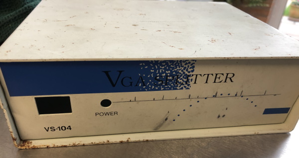
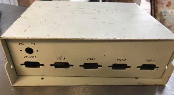
Rough looking I know the project relies on an RS232 serial interface to run and that is a 9-pin D size, identical to the VGA holes on the back! Result!
But I can’t leave it like that, it needs to be sorted out as it is rusty and terrible, not to mention that VGA has nothing to do with a serial powered Z80 computer.
Got to drill some holes in the case to be ready. There are a ton of LEDs and a couple of buttons to add:
LEDs:
Power
Firstly, dismantle the case and spray on some primer:
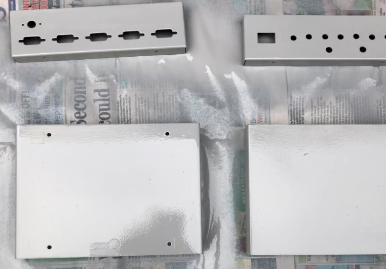
Starting to look much nicer but we are not finished yet.
That grey will have to go and my son suggested blue. So its off to the shop to get some car pain, a nice deep blue colour:
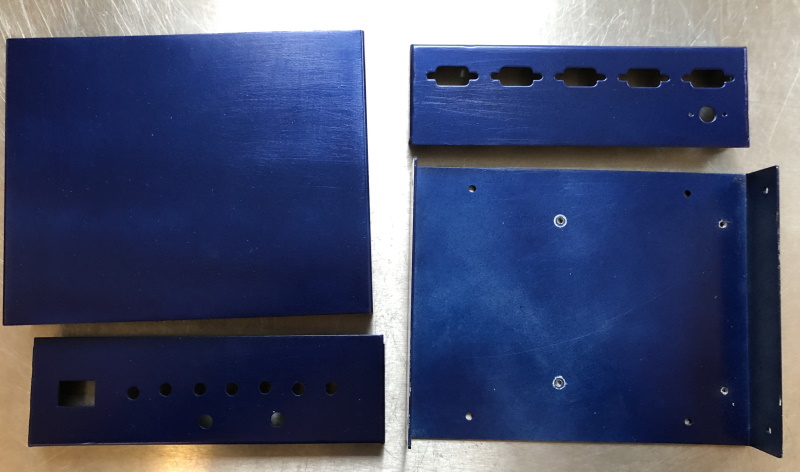
Starting to look better.
I drilled some hold-off post holes to the bottom to allow a positive mounting of the PCB.
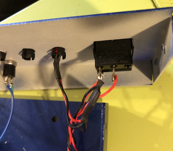
As shown, you can see the stand-off posts that took AGES to find in the parts bin. I knew they were in there, but they managed to hide for hours. Now the board is nicely secure and snug in the case. When this is done it makes the whole thing much easier to work on, and I can cut the wires to length.
I swapped out the LED and push-button holes with pins, so I can mount them to the case.
The original board had pins for the PWR LED. To re-create this, given there is no such thing on the MBC board, a simple circuit is required. It can be made by soldering the components directly and online as shown:
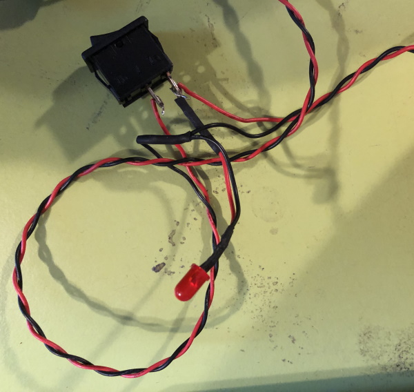
Which is this:
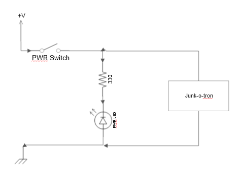
Just a simple 330 Ohm resistor inline with the LED to clamp the current and job done. Used some shrink wrap sleeving to keep things neat.
So the next step is to assemble the unit. Luckily, with the case I have used there is a plethora of 9-pin D socket holes on the back as mentioned. That it is great for the serial, but in the future will use this for other IOs. Also need to figure out the SD card mounting, but that is later as I am keen to get the thing working and see the flashing lights!
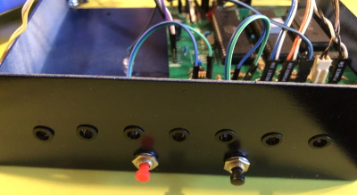
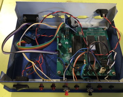
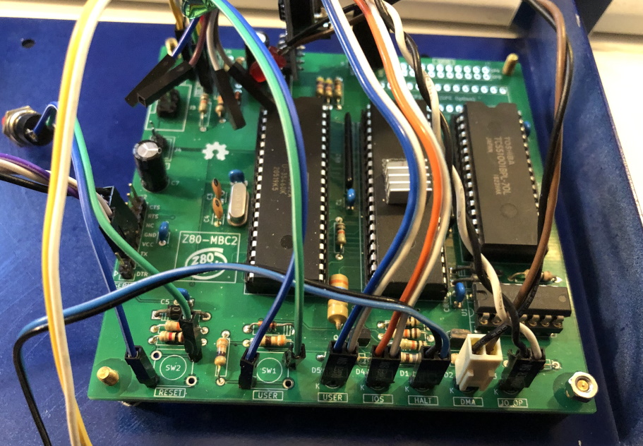
Wow. Getting messy but with the lid on who cares! Seriously, at some point I will tidy this up, I promise. Found that the RTC module has to bend a bit to get it in which is not ideal, but again close the lid and forget about it.
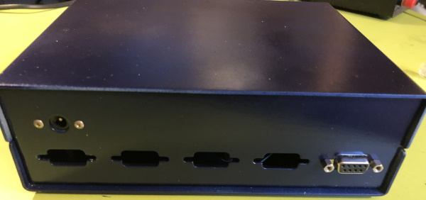
Back panel with the pre-existing DC power socket re-purposed and the serial connection attached.
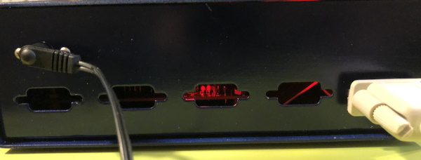
Switched on and you can see some lovely mysterious lights within the case. It is like a miniature world going on in there…
The bottom of the case has 4 nasty screw heads poking out. The case had lost a leg and I didn’t want to buy any (Junk = good) Having a think about this I had a flash that the colour scheme looks similar to Nerf bullets, check these out:
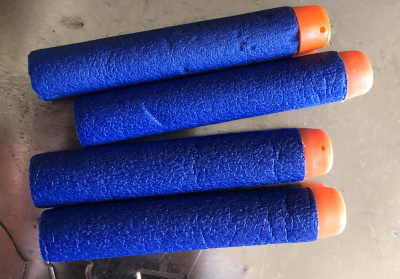
Many parents will know they have a collection of these in a draw or under furniture in their house, they seem to get everywhere. Well, the colour scheme is good, and I actually like the orange contrast. So let’s get 4 dodgy looking ones that don’t fire properly and chop them up:

Then glue them in place
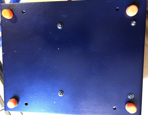
Works very nicely and sits well on its new shoes. the Nerf bullets are lovely a squidgy, feels and looks cool.
The last step here is the front-panel. I created a stencil for the controls and lights, but that is temporary. I have seen other projects using label printers, but I don’t like the aesthetic they give. Here is the temporary stencil I have printed off
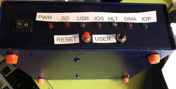
I am thinking about using a clear vinyl wrap for the control panel, both front and back. Then I might be able to create a good-looking set of graphics for the case, with labels and perhaps a logo. I’m thinking Sinclair Spectrum style rainbow? Watch this space.
That is it for now
I will follow up with some more info about actually using the device, it is great to see it flashing, and I have it booting into CP/M which is great fun. I intend to sit it next to my Atari ST and have it on a serial switch, so I can swap to it in the future.