My old neighbour years ago was having a garage clear out. He knew I was into electronics and stuff and said he was throwing out an old black and white portable TV. It was a “Maxim Tv Radio Model Mx11-06” and looked ‘interesting’
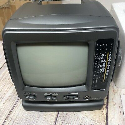
Works off a bunch of C cell batteries or a 12V supply. It was cute, and the radio worked surprisingly well. The issue of course is like most of these sorts of TVs there was only a UHF antenna connection, no other video inputs. That limits its use massively, since analogue TV has not been broadcast for years. There are many old computers knocking around that do still output a UHF signal that this could pick up, however.
Tests of this using my Oric and ZX81 worked… But the picture quality was terrible. REALLY terrible. In this set, there are no presets for the tuning, it is all manual. In fact, that works quite well for old computers are they are always a little different between machines. In and around channel 36… Despite all the fiddling, however, the picture was never good enough to use.
That got to me to wonder how easy it would be to convert this little thing to a composite video input? Despite the age and the lack of colour, it was actually one of the later devices on the market. The component count is greatly reduced over older devices. By this time, a lot of the electronics had become integrated, resulting in fewer components and some larger ICs.
Opening up the case revealed a highly integrated component called the CD5151CP:
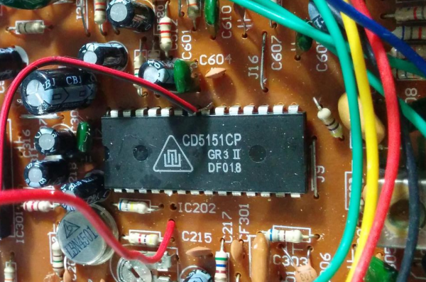
It is not easy to find details about this chip, but I have compiled some stuff, from Chinese and Greek documentation:
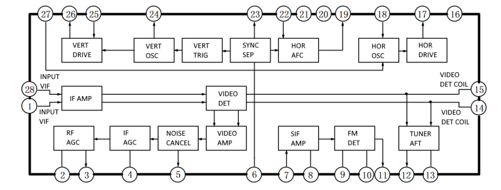
Here is a table showing the pinout functions:
| Pin | Function | Pin | Function |
| 1 | Input VIF | 15 | Video detector coil |
| 2 | RF AGC Delay Adjust | 16 | Vcc2 |
| 3 | RF AGC Output | 17 | Hor Output |
| 4 | IF AGC | 18 | Hor Osc. |
| 5 | Video Output | 19 | Hor Afc Output |
| 6 | Sync Sep. Input | 20 | Vcc1 |
| 7 | Sif Input | 21 | Gnd |
| 8 | Input Bias | 22 | Fbt Pulse Input |
| 9 | Sif Output | 23 | Sync Sep. Output |
| 10 | Sif detector Input | 24 | Vert Osc. |
| 11 | Sound Output | 25 | Vert. Sawtooth |
| 12 | Tuner Aft Output | 26 | Vert. Output |
| 13 | Tuner Aft Coil | 27 | Over Vtg Protection |
| 14 | Video detector coil | 28 | Input VIF |
On the underside of the board you can see the soldered pins:
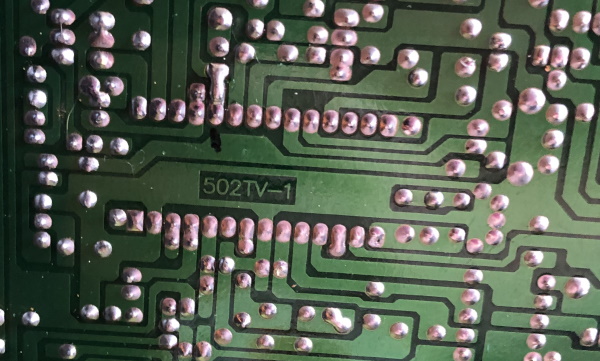
Pin 5 is marked with a black marker pen. That is ‘Video Output’ and is the pin of interest here. The IC takes in the Intermediate Frequency Video input (pin 28 and 1) from the UHV/VHF tuner. Processes this and outputs the sync signals to drive the scan coils. It also handles signal gain and amplification. The video signal is then pushed out of pin 5. I find the following bit of kit really useful when testing video/TV equipment:
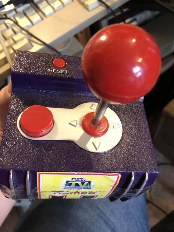
It is a battery operated video game that outputs composite video and RCA audio. Very useful. It can be used to quickly and safely push composite video signals into equipment to test them. Being battery operated, it is bell behaved. At the time of testing it was actually misbehaving badly as I didn’t realize that the batteries were failing. Hooking this up and attaching video shield on the games’ machine to ground on the power input, then the video signal to a probe I was able to change the screen output
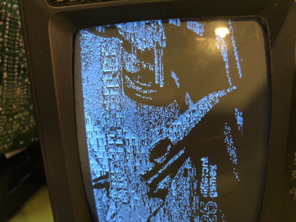
A horrible signal, but there it obviously something there! RESULT!
Some surgery is required to cut the output of the IC so that is no longer pushes the UHF signal into the circuit:
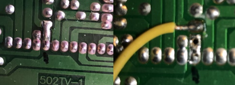
You can see the solder blob that was from the factory. I suspect this was there for a future expansion of this device to take an external signal. On the right is the removed solder from pin 5. It came away really easily. The yellow cable is now the video input signal that was used for testing. So with that in place, the picture looks much better:
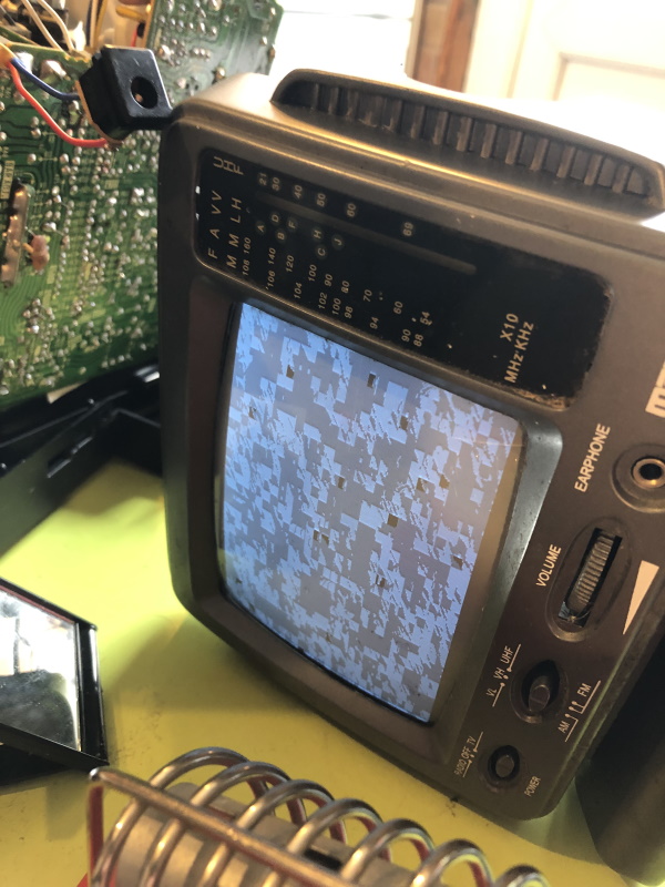
A stable picture… But odd looking… Hold on… These batteries are ancient. Let’s try new ones in the games console:
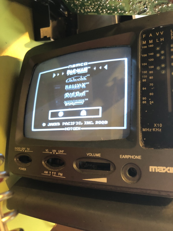
Hey hey! Looking nice!
The picture is a little shaky but really not bad! Next need to replace the cable with something shilded:
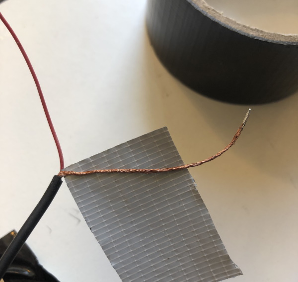
Urgh.. Tape… I really much try and find my shrink wrap box… Will be ok for now. Need a terminal for the input:
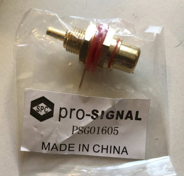
Very flashy! Found this rather nice jack terminal on my parts box, bit too flash for this, but hey!
Drilled a hole in the back of the case. It was next to a power take-off for the batteries, that I removed:
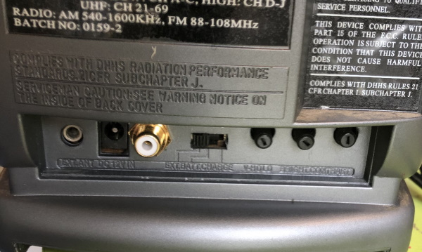
It is a bit tight in there but seemed to work ok.
Now we have a little black and white monitor (no audio at this point, stay tuned… Ugh sorry for the bad joke)
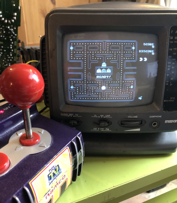
A lovely cute little monitor.
The mod is really easy to do, give it a try and let me know!
Next steps
Sadly it did not work with my ZX81, which was my original intention, but when I revisit I might see if there is a sync issue that is causing that.
Audio is next. The IC also had an Audio Output function on pin 11 can it be that easy?